Ardie's new ear mounted and facing forward to hear the world.
Introduction
Howdy Everyone,
So today I want to talk about some upgrades I gave to Ardie over the weekend. Most of the work involved a lot of coding and debugging, rather than hardware construction. As a result, this blog will be a bit lacking in pictures and such. However, for you code monkeys out there, I will partake in some in depth discussion of the control scheme that went into this particular version of Ardie.
So today I want to talk about some upgrades I gave to Ardie over the weekend. Most of the work involved a lot of coding and debugging, rather than hardware construction. As a result, this blog will be a bit lacking in pictures and such. However, for you code monkeys out there, I will partake in some in depth discussion of the control scheme that went into this particular version of Ardie.
Essentially, I gave Ardie two major upgrades: the ability to throttle his speed, as well as the ability to listen to his environment. To control the throttling, I used the built in pulse-width modulation commands on the Arduino board. This ability is granted via Arduino's built-in AC-DC converter, and it makes the handling of analog signals very intuitive and convenient. To provide Ardie with the ability to hear, I built a small, crude, artificial ear out of a magazine cover and an electret microphone. The single ear gives Ardie the ability to sense sound (especially in the direction of the cone opening), but not the ability to sense the direction the sound is coming from.
Building the Ear
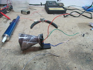
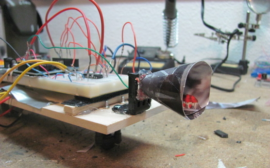
Figure 1: This is the ear I built for Ardie. It uses a small
electret microphone mounted on a right angle bracket
and encompassed by a sound-focusing cone.
electret microphone mounted on a right angle bracket
and encompassed by a sound-focusing cone.
Building Ardie's ear was actually pretty straightforward. I used the following supplies:
-- 1 x electret microphone breakout board.
-- 1 x piece of a magazine cover
-- 1 x plastic right angle bracket (pulled from an old radio)
-- some wire
-- hot glue
All I really did to build the ear was wrap a rectangular piece of tag board (magazine cover) into a cone. I then cut the tip off this cone so it would fit around the circular profile of the microphone. I soldered some wires to each of the three leads on the breakout board (orange = VCC, green = AUD, blue = GND). Next, I glued the breakout board to the face of the bracket and pulled the wires through a hole I cut in the bracket. Finally, I hot glued the cone to the bracket (and probably to the breakout board a bit).
All in all, the process took about 20 minutes and cost me $7.00 or so. It wasn't too bad for a good, quality sensor. The results are shown in Figure 1. To mount the ear, I simply hot glued the bracket to the front of Ardie's chassis. It dawned on me, about the time I was gluing, that I could have used Velcro to attach the bracket so that it would be removable in the future, but by then it was too late.
The wiring was very simple and straightforward. I connected the Vcc lead (orange wire) for the ear to a node on Ardie's breadboard that was connected the the Arduino 5V pin. I connected the GND lead (blue) to the ground rail on Ardie's breadboard. Finally, I fed the AUD lead (audio signal) into the Analog Input pin 0 on the Arduino board. I used solderless leads for all of these connections so that they would not be permanent.
Pin Rewire

Figure 2: The H-bridge has been rewired
such that all outputs from the Arduino
to the H-bridge are connected through
pins that allow pulse-width modulation.
such that all outputs from the Arduino
to the H-bridge are connected through
pins that allow pulse-width modulation.
Once I had the ear built and mounted on Ardie, I was ready to teach Ardie the difference between walking and running. To do this, I decided to use the Arduino's pulse-width modulation capabilities to control the amount of power sent to the H-bridge. In my previous demonstration of Ardie, I enabled the H-bridge using a digitalWrite(motorsPinEnable, HIGH) command. This set a steady 5 volts of potential along pin 2 to the H-bridge, which powered the H-bridge on.
Pulse-width modulation allowed me to send a varying amount of power over a set time period along any of the Arduino's PWM pins (3, 5, 6, 9, 10, 11). As such, I had to rewire my H-bridge so that it was connected only to the output pins labeled PWM (3, 5, 6, 9, 10, 11). The new wiring is reflected in Figures 2 and 3.
(Please note that I could have rewired the H-bridge such that all nodes connected to Pin 2 were connected to Pin 3, since I send my analog signal along the power node to the H-bridge, rather than to each motor separately. However, I rewired everything in order to open up performance options for Ardie in the future).
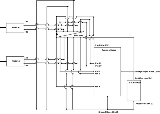
Figure 3: This is the full circuit diagram for Ardie as he has been rewired to allow output along pulse-width modulated pins only.
It is difficult to design a circuit that can deliver any amount of potential between a high and low setting. Effectively, a potentiometer must be used and automatically commanded to allow for this capability. Pulse-width modulation grants designers a cheat around that difficult task. In a PWM signal, a single high potential is set across a circuit path (in our case, 5 volts). However, rather than that potential being delivered 100% of the time, it is turned on and off for some portion of a set time period. For instance, in a given time period, the signal might spend 70% of the time on (high) and 30% of the time off (low, or zero). Since the on-off pulses are sent very rapidly, this has the effect of mimicking a circuit that is operating at 70% of the full potential (0.70 * 5 volts = 3.5 volts). Thus, using the PWM pins on the Arduino board gave me the ability to deliver an arbitrary "apparent" voltage to the H-bridge, effectively throttling it. This is reflected in the source code (at the bottom of this blog) where I utilize the analogWrite command on the motorsPinEnable pin for each direction subroutine.
To learn more about Arduino's PWM capabilities, please see this site.
Once I had Ardie's drive setup in such a manner that it could be throttled, it was time to read and process the input recorded by the microphone.
To learn more about Arduino's PWM capabilities, please see this site.
Once I had Ardie's drive setup in such a manner that it could be throttled, it was time to read and process the input recorded by the microphone.
Filtering and Mapping the Input
It turns out that the primary challenge of this particular project was processing the input from the microphone in such a manner that it sent meaningful commands to Ardie's drive system. One nice thing about the Arduino language is that it implements a built in command called map() that allows the programmer to scale two sets of data against each other. I'll demonstrate the use of this command in the code snippet below:
  // Read the microphone input.
   Mic_In = analogRead(Mic_Pin);

   if(Mic_In < 400 || Mic_In > 1023){
       // Reading too low or too high, jump to next loop.
   }else{
    ...
     Throttle = map(Mic_In, 400, 1023, 100, 255);
     Run_Time = map(Mic_In, 400, 1023, 1000, 10000);
    ...
   }
Notice the line near the end of that snippet where I set up the Throttle variable. I feed the map command five inputs. The first input is the value that I want to interpolate to. In this case, I am setting the value of Throttle based on the value read into the Mic_In command (set at the top of the snippet by reading the microphone). I then provide four more values to the map command that set up two linear scales to link together. Essentially, map links the value of 400 to the value of 100. It then links the value of 1023 to the value of 255. Finally, it takes the value stored in the Mic_In variable and sets an interpolated value for Throttle between 100 and 255. It thus ties the numerical values between 400 and 1023 to the values between 100 and 255 in a linear manner. This is useful because the Arduino board processes analog input signals to have a value between 0 and 1023. However, it can only send analog output signals between 0 and 255. Thus, the programmer must map the input to an output manually. A slightly better explanation of this command can be found here.
You probably noted, however, that I did not map the zero value of the analog input signal to a zero value of the analog output signal. This was intentional. After toying around with the analogWrite commands and some manually input data, I found that any analog output signal (duty cycle) that was less than about 100 would not turn the motors when Ardie was on the ground. Enough power wasn't getting sent to the motors. Thus, I decided to make 100 the lowest possible limit for my Throttle setting.
Secondly, you will probably note that the lowest value of the input signal allowed was 400. If you take a look at the full source code at the bottom of the blog, you will see a series of Serial.print(...) commands. These commands enabled my Arduino board to output data to the serial monitor in the Arduino integrated development environment. An in depth exploration of this feature is beyond the scope of this blog. However, you can read more about the serial monitor here. For now, what you need to know is that I used the serial monitor to import the values of Mic_In, Throttle, and Run_Time onto my computer for analysis. I enabled the microphone in what was supposed to be a quiet room and let it run for a short amount of time to collect the data displayed in Figure 4.
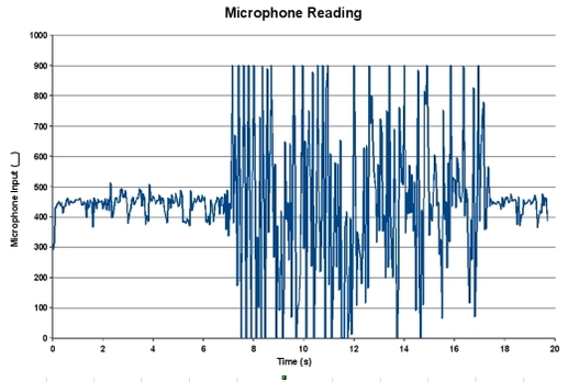
Figure 4: Microphone input readings to Arduino board. Right-click and save the image to enlarge it.
As is apparent in the above figure, the typical background noise that the microphone was reading was between about 400 and 500 units. The large amplitude readings occurred when I played a tone from my cell phone in front of the microphone. The data, therefore, suggested that a filter needed to be implemented so that a basic background noise level of 400 would result in the lowest possible throttle (100). Hence my mapping of 400 to 100 in the above code. You will also notice that I used a similar mapping command to set the Run_Time for the motor commands. In that command, I mapped the microphone input readings of 400 and 1023 to 1,000 and 10,000 respectively. This gave the motors an operational run time of one to ten seconds (delay commands are processed in milliseconds by Arduino).
The final filter that I implemented also involved the encompassing if-else statement depicted in the code snippet at the top of this section. Embedding all of the operational code in an if-else statement allowed me to process the microphone input readings that fell between about 400 and 1023 by using the appropriate logic in the conditional of the if statement { if(Mic_In < 400 or Mic_In > 1023) ... }. This statement set up Ardie in such a manner that he would not process any commands unless the microphone reading fell between 400 and 1023 (notice that the if conditional results in no code processed, while the else conditional encompasses all of the signal processing commands). For ambient noise levels less than 400, Ardie would take a different reading before acting. This prevented Ardie from inadvertantly setting a command or throttle setting to be less than zero. Feeding a negative number to the analogWrite command to the motors would, effectively, lock Ardie into processing a never-ending command (which, incidentally, I did several times while debugging this program).
With the appropriate filters established, I was finally ready to give Ardie some extraordinarily basic control software.
Control Schemes
I built two basic operational control modes into Ardie which are depicted in the code snippet below. Notice that the while(){} schema is completely commented out. I have not yet implemented this command structure, but if you would like to try it, feel free. Simply uncomment the relevant code and comment out the if-else structure.
...
 if(Mic_In >= 710){
       backward(Run_Time, Throttle);
     }else{
       forward(Run_Time, Throttle);
     }
 ...
     /*
     while(Mic_In >= 710){
       backward(Throttle);
     }

     while(Mic_IN < 710){
       forward(Throttle);
     }
     */
 ...
These two modes are pretty straightforward. Remember the only microphone in readings that we are processing fall between 400 and 1023. This leaves the half-way point at about 710 (with liberal rounding bias). Thus, the first if-else statement basically tells Ardie to move backward (defined as the direction opposite that which the microphone is facing) at a Run_Time and Throttle level proportional to the microphone reading taken (remember those map commands above). Effectively, it is telling Ardie to run from loud noises.
The else portion of the statement encompasses all microphone readings below 710. This qualified, in my opinion, as a quiet or 'safe' noise. Thus, if Ardie is only reading such low noise levels, he creeps forward slowly (Throttle proportional to microphone reading) in very small intervals (Run_Time, the time that the motors spend enabled, is also scaled to the low microphone reading).
This has the basic effect displayed in Video 1:
At present, this is the control mode that Ardie is operating in. He creeps forward slowly in small bits until he hears a loud noise. Then he runs like hell (like all good animals trying to preserve their own existence do). The second control scheme, implemented via the while loop, should be very similar. In order to implement that scheme, all of the motor command subroutines defined later in the code need to be modified such that they simply turn on and never turn off (disable the Run_Time input). These modifications are stored in comments in each subroutine of the full source at the bottom of this post.
If these changes are implemented, and the while(){} control mode is uncommented, then Ardie should, theoretically, continue forward without stopping until he hears a loud noise. He should then run, quickly, away immediately. As soon as the sound disappears, he should start moving forward again. Thus, his motion would be more continuous, rather than discreet. If I get a chance to test and record this behavior I will post a second video below later.
If these changes are implemented, and the while(){} control mode is uncommented, then Ardie should, theoretically, continue forward without stopping until he hears a loud noise. He should then run, quickly, away immediately. As soon as the sound disappears, he should start moving forward again. Thus, his motion would be more continuous, rather than discreet. If I get a chance to test and record this behavior I will post a second video below later.
Lessons Learned
This particular upgrade taught me a few very important lessons. First and foremost, it reminded me of the importance of maintaining gumption (see my philosophy page). I had Ardie's ear built in less than an hour. I had his connections wired and ready to go in less than five minutes. I had his control software written in about an hour and, as soon as I turned him on, he jumped into a failure mode where the motors locked on and stayed on. That was pretty disheartening.
It took me more than a day and a half of debugging the software and circuit before I figured out that I needed to input a sensor reading filter. By the end of the first night, I felt both intellectually and physically drained. Though I very much wanted to fix Ardie that night and finish him, I realized my weariness would have led to my making many basic errors. Thus, I got some sleep and picked up the problem the next day. So, lesson 1: avoid the gumption trap of overworking. Above all else, a high level of gumption must be maintained when working on anything.
Lesson two came with the realization that I needed to filter the input better. My original input filtering scheme involved my two map commands, but no if-else statement. As a result, every time the Arduino board read a value less than 400 on the input signal wire, it mapped a very low Throttle and Run_Time value. In some cases, these were negative and, thus, the motors would get stuck on. In retrospect, it makes perfect sense that mapping two non-zero low bounds on my ranges could result in this possibility. However, at the time of the programming, it was not so apparent to me. It took a full plot of the data for me to realize that the microphone was getting saturated and, thus, sending a zero value to the Arduino board. Lesson two in this lab, therefore, was one that I learn over and over again as an engineer:
The most trivial assumptions can result in total system failures.
As an engineer that last sentence and lesson is very important. In my field of work, the aerospace field (and probably in most others) we call these types of glitches in software and hardware, "failure modes." Many aerospace companies employ armies of engineers in order to flush out all of the potential failure modes for a given system. While my programming involved low-voltage DC motors and a few dozen lines of code, most satellites and rockets are extraordinarily complex machines. They can involve hundreds of actuators (motors, servos, deployables, etc.) that are controlled by dozens of controllers (microcontrollers, computers, motor controllers, servo controllers, etc.) that may involve, literally, hundreds of thousands of lines of control software. Finding failure modes in such complex systems, therefore, becomes a very detail intensive process.
To complicate matters, many aerospace systems only fly once. If a failure mode is not fully understood before a mission launches, it could cause a catastrophic failure (read as, "epic-level explosion") with, potentially, no second try. If a gimbal controller on a rocket nozzle glitches and the rocket smashes into the ground, you don't get to fly that million dollar rocket or million dollar payload a second time. Thus, it is very, very, very important, in my opinion, for engineers to spend time tinkering on stuff to gain more and more exposure to possible failure modes of various types of systems. While I would never use a map command in satellite flight software, I most certainly will check for the possibility of unexpected negative values being passed to my hardware by accident from now on. Or, for an even broader lesson, I will remember to build checks into my software to ensure that the only potential values passed to my hardware will be those that I need and expect.
All in all, this was a fun system development lesson. I look forward to any comments and questions you all may have. As Ardie grows in complexity (and he will, I have a rangefinder to install on him), I will, no doubt, be exposed to even more frustrations and confusions. Nonetheless, I look forward to the challenge. Overcoming obstacles is what we engineers do after all. ;)
So until next time, I wish you all good hacking and fun tinkerings.
Cheers,
Brady C. Jackson
Full Source Code
/*
 Author: Brady C. Jackson
 Date Written: 10/16/2010
 Date Last Modified: 10/16/2010
 Name: Ardie_Throttle_Demo

 Purpose: This sketch will program Ardie v1.1 to move based on
          the sensory information read from a single microphone.
          As long as the sound level is below the 1/2 mark of the
          microphone's dynamic range, Ardie will gradually take
          short, slow steps forward at a rate proportional
          to the sound detected. If the sound gets louder than
          the half way point, Ardie will run away, also at a rate
          proportional to the sound level.
 */

 int Mic_In = 0;  // Prime microphone reading to be zero.
 int Throttle = 0; // Prime the throttle setting.
 int Run_Time = 0; // Prime run time.
 int Mic_Pin = 0; // Declare microphone reading to come on pin 0.

 // Declare all motor pins
 int motor_B2 = 10;
 int motor_B1 = 11;
 int motor_A2 = 9;
 int motor_A1 = 6;

 int motorsPinEnable = 3;  // Declare the pin which turns on the H-bridge

 void setup() {

   // Enable all motor pins for output.
   pinMode(motor_B2, OUTPUT);
   pinMode(motor_B1, OUTPUT);
   pinMode(motor_A2, OUTPUT);
   pinMode(motor_A1, OUTPUT);
   pinMode(motorsPinEnable, OUTPUT);

   // Turn on H-bridge
   digitalWrite(motorsPinEnable,HIGH);

   // Enable serial output to computer
   Serial.begin(9600);

 }

 void loop() {
   // Read the microphone input.
   Mic_In = analogRead(Mic_Pin);

   if(Mic_In < 400 || Mic_In > 1023){
       // Reading too low or too high, jump to next loop.
   }else{
     /*
     Map values such that minimum throtttle (100) and minimum
     Run_Time (1,000 ms = 1 second) occurs when the microphone
     picks up a reading of 400. Also require a maximum microphone
     reading of 1023 in order to hit full throttle (255) and
     maximum Run_Time of 10,000 ms or 10 seconds).
     */

     Throttle = map(Mic_In, 400, 1023, 100, 255);
     Run_Time = map(Mic_In, 400, 1023, 1000, 10000);

     /*
     If Ardie encounters a very loud noise (greater than 1/2
     the dynamic range of the microphone [Mic_In = 710]), then
     run away (backwards) for a long time at a high speed
     (proportional to level of noise). Otherwise, move press
     at a speed proportional to detected ambient noise.
     */

     if(Mic_In >= 710){
       backward(Run_Time, Throttle);
     }else{
       forward(Run_Time, Throttle);
     }

     // Print data to serial display on computer
     Serial.print("Microphone reading = ");
     Serial.print(Mic_In);
     Serial.print("\t Throttle level = ");
     Serial.print(Throttle);
     Serial.print("\t Run_Time = ");
     Serial.print(Run_Time);
     Serial.print("\n");

     // Take a breather
     delay(500);

     /*
     Set up to while loops so that Ardie pushes forward as long
     as the noise is below 710, but runs away if the noise detected
     rises above 710
     */

     /*
     while(Mic_In >= 710){
       backward(Throttle);
     }

     while(Mic_IN < 710){
       forward(Throttle);
     }
     */

   }
 }

 void backward(int on_time, int duty_cycle){
     //digitalWrite(motorsPinEnable,HIGH);
     // Throttle motors by sending pulse-width modulated duty
     // cycle to the H-bridge power pin (2)
     analogWrite(motorsPinEnable, duty_cycle);

     digitalWrite(motor_B2, LOW);
     //analogWrite(motor_B1, duty_cycle);
     digitalWrite(motor_B1, HIGH);

     digitalWrite(motor_A1, LOW);
     //analogWrite(motor_A2, duty_cycle);
     digitalWrite(motor_A2, HIGH);

     delay(on_time);
     digitalWrite(motorsPinEnable,LOW);
 }

 void forward(int on_time, int duty_cycle){
     //digitalWrite(motorsPinEnable,HIGH);
     // Throttle motors by sending pulse-width modulated duty
     // cycle to the H-bridge power pin (2)
     analogWrite(motorsPinEnable, duty_cycle);

     digitalWrite(motor_B1, LOW);
     //analogWrite(motor_B2, duty_cycle);
     digitalWrite(motor_B2, HIGH);

     digitalWrite(motor_A2, LOW);
     //analogWrite(motor_A1, duty_cycle);
     digitalWrite(motor_A1, HIGH);

     delay(on_time);
     digitalWrite(motorsPinEnable,LOW);
 }

 void left(int on_time, int duty_cycle){
     //digitalWrite(motorsPinEnable,HIGH);
     // Throttle motors by sending pulse-width modulated duty
     // cycle to the H-bridge power pin (2)
     analogWrite(motorsPinEnable, duty_cycle);

     digitalWrite(motor_B2, LOW);
     //analogWrite(motor_B1, duty_cycle);
     digitalWrite(motor_B1, HIGH);

     digitalWrite(motor_A2, LOW);
     //analogWrite(motor_A1, duty_cycle);
     digitalWrite(motor_A1, HIGH);

     delay(on_time);
     digitalWrite(motorsPinEnable,LOW);
 }

 void right(int on_time, int duty_cycle){
     //digitalWrite(motorsPinEnable,HIGH);
     // Throttle motors by sending pulse-width modulated duty
     // cycle to the H-bridge power pin (2)
     analogWrite(motorsPinEnable, duty_cycle);

     digitalWrite(motor_B1, LOW);
     //analogWrite(motor_B2, duty_cycle);
     digitalWrite(motor_B2, HIGH);

     digitalWrite(motor_A1, LOW);
     //analogWrite(motor_A2, duty_cycle);
     digitalWrite(motor_A2, HIGH);

     delay(on_time);
     digitalWrite(motorsPinEnable,LOW);
 }

 void stop(int on_time){
     digitalWrite(motorsPinEnable,LOW);
     delay(on_time);
     digitalWrite(motorsPinEnable,LOW);
 }

 RSS Feed
