Ardie Version 1.0
Introduction
Howdy Again Everyone!
So today I am going to talk about my latest robot platform that I slapped together in the last few weeks.
First, I need to give credit where credit is due. Batist Leman developed this particular robot before I ever did, and that's where I got the idea. Batist eventually went on to hook his version of Ardie up to a Playstation controller, and he could drive the robot that way. I am hoping to take my version of Ardie in a different direction.
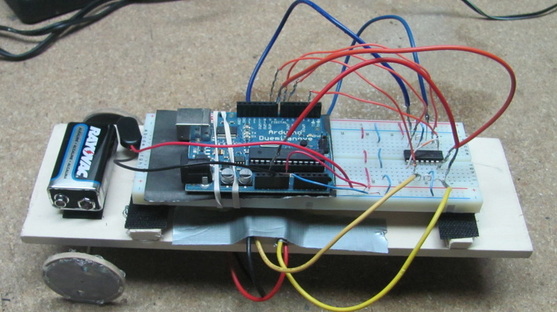
Ardie is constructed, essentially, of an Arduino micro-controller rubber banded to a breadboard with an H-bridged wired up to two drive motors. This simple nature of Ardie allows him to be developed and tinkered upon to quite a degree. I will eventually develop Ardie to read sensor inputs and use them to control some sort of added functionality (maybe a small arm, or a pointer, or something). This should help me refine and develop my control system software development skills with time.
Ardie was relatively cheap to build (I think about $50 by the time all was said and done), and simple to put together. Thus, if you are interested in building a simple Arduino powered robot, read on.
So today I am going to talk about my latest robot platform that I slapped together in the last few weeks.
First, I need to give credit where credit is due. Batist Leman developed this particular robot before I ever did, and that's where I got the idea. Batist eventually went on to hook his version of Ardie up to a Playstation controller, and he could drive the robot that way. I am hoping to take my version of Ardie in a different direction.
Ardie is constructed, essentially, of an Arduino micro-controller rubber banded to a breadboard with an H-bridged wired up to two drive motors. This simple nature of Ardie allows him to be developed and tinkered upon to quite a degree. I will eventually develop Ardie to read sensor inputs and use them to control some sort of added functionality (maybe a small arm, or a pointer, or something). This should help me refine and develop my control system software development skills with time.
Ardie was relatively cheap to build (I think about $50 by the time all was said and done), and simple to put together. Thus, if you are interested in building a simple Arduino powered robot, read on.
Parts List
First things first. In order to build Ardie, I needed to collect the appropriate parts for him. These parts are listed below:
- 1 x Dual Motor Gear Box
- 1 x Omni Ball
- 1 x SN754410 H-Bridge
- 1 x Duemilanovae Arduino Board (actually, any Arduino will do, I just used this one)
- 1 x Simple Breadboard
- Something to use as wheels
- A strip of balsa wood
- Some velcro
- Some 9 V batteries
Programming the Arduino
Before I started assembling anything, I decided to cut my teeth on the Arduino board. The Arduino project is a very interesting project, and the official website can be found here. Essentially, some folks got together and wrote an open source micro-controller language for use with Atmega chips. This language, along with the appropriate hardware, allows for the quick and simple programming of micro-controllers which can then be used to manipulate systems as necessary. They can be used as embedded computer systems for internal processing. They can be used to process analog inputs and write digital outputs. They can be used for all sorts of cool stuff (just do a net search for "cool Arduino projects" to see what I mean).
I decided to use an Arduino micro-controller so that I could rewrite and develop new programs quickly and easily for my robot. Repeated hacking and tinkering on this robot will be crucial, so I didn't want to use a programming platform whose syntax would become an obstacle. Once I decided on the Arduino platform, I needed to download the IDE (which comes with an integrated compiler) from here. I downloaded the Linux version (because Microsoft is a shit OS), and had to do a few simple hacks to get it working. You should look up a few tutorials and how-to's for your OS and distribution version before downloading everything, just so you can know what to expect.
Anyways, once I had the IDE up and running, I liberally hijacked Batist's code and modified it for my own purposes (I reduced the delay between motor functions, and changed the order). I then compiled the code in the IDE (things are pretty self explanatory once you start using the software) and flashed the sketch (that's what we call Arduino programs) to the Arduino chip (which I had connected to my computer via USB). The source code for my current version of Ardie can be found at the very bottom of this blog entry.
With my chip programmed, it was time to hook the chip up to something.
Drive and Suspension
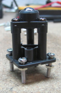
Figure 1: The omni-ball front wheel
requires you to assemble it yourself.
requires you to assemble it yourself.
While attending school for aerospace engineering, we were constantly inundated with discussions about systems level engineering. Systems engineering refers to the process of bringing together many complicated subsystems to work together to form an even more complicated, and powerful, final system. With robots, systems engineering is also a very important factor. For instance, Ardie not only consists of an Arduino chip, but also of a chassis, a drive system, and a prototyping board. As time goes on, I will scale him up by adding other subsystems such as sensor suites and, possibly, some other attachments or controllers. Thus, I found that, while building Ardie, I wasn't simply building a robot, but I was building a system. The first subsystem I worked on was the controller (the Arduino programming). The next subsystem to work on was the drive system.
Ardie needed to be mobile. To meet this challenge, Batist designed a drive system that consisted of a geared motor box and an omni-ball third wheel. The omni-ball on one end of Ardie's body allows that end to move in any direction: forwards, backwards, right, or left. However, this means that Ardie needs to have directional control built into his two drive wheels, which are attached to the axles of the dual motor box. Both the dual motor box, and the omni-ball assembly arrive in an unassembled manner. Thus, my first step was to follow the assembly instructions for both to get the drive system built. The final omni-ball assembly is depicted in Figure 1 while Figure 2 depicts all of the parts of the dual motor box.
Ardie needed to be mobile. To meet this challenge, Batist designed a drive system that consisted of a geared motor box and an omni-ball third wheel. The omni-ball on one end of Ardie's body allows that end to move in any direction: forwards, backwards, right, or left. However, this means that Ardie needs to have directional control built into his two drive wheels, which are attached to the axles of the dual motor box. Both the dual motor box, and the omni-ball assembly arrive in an unassembled manner. Thus, my first step was to follow the assembly instructions for both to get the drive system built. The final omni-ball assembly is depicted in Figure 1 while Figure 2 depicts all of the parts of the dual motor box.
Both the omni-ball and dual motor box assembly are pretty straight forward. Instructions come with each subassembly and discuss how to put the pieces together in the configuration you want. The dual motor box assembly has three possible assembly configurations: A, B, and C which are discussed in detail in the assembly instructions. I opted to use configuration A for my version of Ardie, but I think you could probably use configuration B just as well.
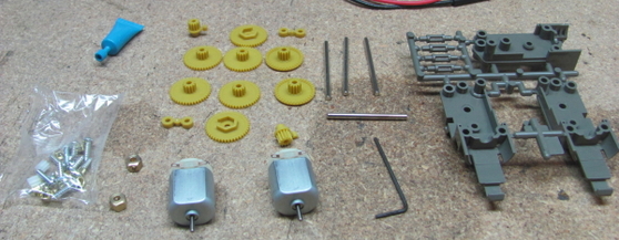
Figure 2: The dual motor box comes entirely disassembled so you can build it yourself. What fun!
Assembly of the motor box and omni-ball requires little more than a screwdriver and a patient hand. It is important to remember that you are working with very small parts while putting these components together. As such, keep your work area well lit, and be gentle with your movements. Having some of those tiny screws and nuts go bouncing away into dark corners can be quite the gumption trap.
Another brief piece of advice, I recommend soldering lead wires to the two motors that come with the dual motor box assembly before doing anything else. Having the wires soldered to the motor leads initially saves you from the hassle of having to maneuver your soldering iron around the rest of the gear assembly. Failure to do this could result in melting part of your gear assembly and that would be terrible.
Figure 3 depicts the gear box partially assembled. As you can see, this subsystem requires some precision modeling. Take your time and double check all of the instructions. Things should go well if you are patient.
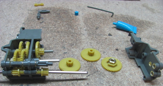
Figure 3: Assembly of the dual motor gear box is relatively straightforward. I configured it into the
type 'A' configuration described in the instructions.
type 'A' configuration described in the instructions.
With the drive subsystem assembled and awaiting installation, I was ready to move onto the circuit building.
Breadboarding the Circuit
The most important diagram you can have when working on an electronics project is the circuit diagram. That said, I drew up a full circuit diagram for Ardie v1.0 and attached it below (Figure 4). The diagram was created using the very useful, though somewhat limited, open source software: Dia. The print is fairly small in this blog, so feel free to download the entire JPEG and view it up close. There are no legal ramifications for downloading any of the diagrams or pictures off of my websites because, frankly, I am too lazy to pursue you legally.
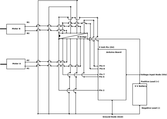
Figure 4: Entire Circuit Diagram. The diagonal line across the H-bridge represents the jumping of those two pins together.
It is important to note the A1, A2, B1, and B2 designations of the two motors. Essentially, 1 is supposed to represent the same electrical tab on each of the motors. Thus, Motor A would be "upside down" in the above diagram since its A1 tab is in the opposite spot that B1 is on motor B. I drew the diagram this way because the motors mount in the dual motor gear box assembly as mirror images of each other. In other words, if "tab 1" is the top tab on motor B when motor B is mounted in the gear box assembly, then "tab 1" will be the bottom tab on motor A when motor A is mounted in the gear box assembly because the tab leads both point outwards on either side of the assembly. That may be a bit confusing, but if you end up hooking up your entire circuit and notice that the direction commands being processed are in the wrong order, or are just wrong, then try swapping the H-bridge connections for one of the motors and it may fix your problem.
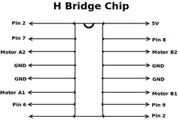
Figure 5: Diagram of H-bridge pin connections.
I also wanted to give a close up of the H-bridge configuration of the circuit because this is a major portion of the circuit controller system. Figure 5 depicts the H-bridge with each pin connection labeled. These connections should sync up to the labels on your Arduino board exactly. The connections that are labelled as the same thing (such as GND, or Pin 2) can be jumped to a common row on the bread board to simplify things.
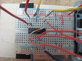
Figure 6: This is a picture of my H-bridge all
wired up and ready to go. Notice how I
jumped both ground (-) rails and hot (+)
rails together on the breadboard.
wired up and ready to go. Notice how I
jumped both ground (-) rails and hot (+)
rails together on the breadboard.
A rougher copy of these schematics can be found on Batist's blog about this robot as well. I used his diagrams to put together my version of Ardie and would like to thank him for making them available to me. Once I got the H-bridge of the circuit wired into the breadboard and Arduino board, I rubber-banded the Arduino board to the breadboard to lock things in place. Figure 6 shows my H bridge connections up close (though you can't see where each wire terminates on the Arduino board). Notice that the lower left and upper right corners of the H-bridge are jumped together. This is because both pins connect to Pin 2 on the Arduino board. Also note that the '-' and '+' rails on the breadboard are jumped together. The '-' rail is connected to the GND pin on the Arduino board, while the '+' rail is connected to the Vin Arduino pin as well as the positive 9 v battery lead.
Finally, you'll notice that I soldered my own breadboard leads to each wire because A) it's very good soldering practice, and B), it allowed me to swap wires in and out of various breadboard holes as necessary. For a final design you might consider practicing better wire management techniques as well as wrapping most of your wire leads in electric tape so they don't accidentally short.
Chassis and Final Assembly
With the controller circuit, the drive motors, and the omni-ball assemblies completed, I was ready to start piecing the entire robot together. My first step was to build a simple chassis for Ardie out of balsa wood. I found a piece of relatively thick balsa wood that was a bit longer and wider than my breadboard for the chassis. The extra width and length would allow me to mount the breadboard on the chassis with a little extra room for further Ardie additions as I mod him in the future.
With the chassis selected I measured out appropriate mounting locations for the omni-ball and dual motor assembly as shown below in Figure 7. The nice thing about balsa wood is that you can do all of your markings with a pencil right on the wood (as well as your math). I made certain to center the omni ball and the dual gear box to the best of my abilities. This, I figured, would allow for more fluid motions of the vehicle as off-center forces create asymmetric torques on the body (which can suck from both a structural and controllable perspective).
With the chassis selected I measured out appropriate mounting locations for the omni-ball and dual motor assembly as shown below in Figure 7. The nice thing about balsa wood is that you can do all of your markings with a pencil right on the wood (as well as your math). I made certain to center the omni ball and the dual gear box to the best of my abilities. This, I figured, would allow for more fluid motions of the vehicle as off-center forces create asymmetric torques on the body (which can suck from both a structural and controllable perspective).
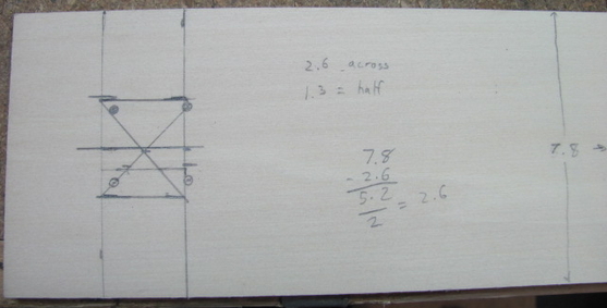
Figure 7: I made certain to center the omni-ball and dual motor box on the baseboard so that Ardie would have fluid motions.
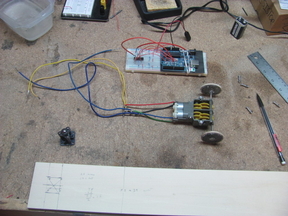
Figure 8: With all of my subassemblies assembled,
I was ready to start sticking the big parts together
I was ready to start sticking the big parts together
With the chassis marked, I started drilling into it using a simple cordless drill. There was no need for the 10,000 rpm's of my Dremmel for balsa wood. I should note, however, that I selected a slightly oversized drill bit when drilling the mounting holes since I fastened the omni-ball and dual motor assembly with screws and nuts, rather than wood screws. Both options are provided in the packages that you buy, so your choice of mounting is up to you. I wanted to be able to detach and redesign the drive system as time went on, so having an easily removable nut-screw combination suited my needs best.
Figure 8 shows the final subsystems on my workbench awaiting assembly. You can see the extra long wires attached to the motors in that picture.I trimmed these wires down and taped up the solder points to prevent any circuit shorting later on in the build. For wheels, I used two pulleys that I ripped out of an old, gutted tape cassette payer. I hot glued some rubber bands to them for traction. The pulleys were not the exact same shape, but they were the same diameter so they mostly work.
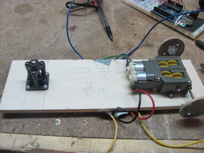
Figure 9: The motors and omni-ball were screwed
to the baseboard. I used hot glue and velcro to
attach everything else.
to the baseboard. I used hot glue and velcro to
attach everything else.
With all my holes drilled and my subassemblies together, I started putting on the final touches. I screwed the omni-ball and and drive-motor wheel assemblies to the main baseboard. I taped the motor leads to the baseboard so that no structural load would be put on the solder connections at the motor. I cut two small risers out of excess balsa wood and hot-glued them to the top of the chassis. I lined the top of these risers with Velcro while lining the bottom of my breadboard with two strips of Velcro. This allowed me to simply push the breadboard and circuit onto the chassis and remove it as I felt necessary for future hacking.
I also used Velcro to attach the 9 volt battery to the back of the chassis. This allowed me to quickly and easily attach the power cable to the battery to bring Ardie to life. I used a simple 9 volt battery connector with loose positive and negative leads to connect the battery to the Arduino board. The positive lead connected to the Vin node (positive rails on the breadboard) while the negative lead was connected to the GND node (negative rails).
And, with power, came....
....LIFE! Mwahahahahaha! (see Video 1).
Lessons Learned
Okay, so maybe that doesn't quite qualify as life. In fact, Ardie doesn't really even qualify as a robot according to the guiding definition I use on my robots page. Ardie, at this point, is nothing more than a dumb vehicle that drives in a falling leaf motion repeatedly. In order for him to grow into a real robot, I need to add some sensors so he can process his environment. Until then, however, he stands as one of the funnest things I've had the pleasure of building yet.
As for lessons learned this build, well, there weren't many. For the first time, everything went relatively smoothly. I suppose that's what happens when you give yourself adequate time and preparation.
However, I should note that I did learn how awesome Arduino chips are. I also reinforced my lessons from Symet that having a prototype breadboard configuration is invaluable. Finally, I learned that all those years building model jet planes and Lego castles did pay off. Assembling those drive motors would have been very intimidating without that experience. So for all you young engineers out there, keep playing with those awesome toys. It really will pay off.
For now, I suppose that is about all. I hope you all enjoyed the read. Feel free to contact me if you would like more pictures, info, or hints about building this robot. I have a lot of material that I didn't use because this entry was long enough.
So until later,
Best of luck, and good building!
Brady C. Jackson
Arduino Source Code
// Originally by Batist Leman
 // Modified by Brady C. Jackson

 int motor1Pin1 = 8;
 int motor1Pin2 = 9;

 int motor2Pin1 = 7;
 int motor2Pin2 = 6;

 int motorsPinEnable = 2;

 int ledPin = 3;

 void setup() {
   pinMode(motor1Pin1, OUTPUT);
   pinMode(motor1Pin2, OUTPUT);
   pinMode(motor2Pin1, OUTPUT);
   pinMode(motor2Pin2, OUTPUT);
   pinMode(motorsPinEnable, OUTPUT);
   pinMode(ledPin, OUTPUT);

   digitalWrite(motorsPinEnable,HIGH);
 }

 void loop() {
     forward(1500);
     stop(1000);
     right(1500);
     stop(1000);
     backward(1500);
     stop(1000);
     left(1500);
     stop(1000);
 }

 void forward(int del){
     digitalWrite(motorsPinEnable,HIGH);
     digitalWrite(motor1Pin1, LOW);
     digitalWrite(motor1Pin2, HIGH);

     digitalWrite(motor2Pin1, HIGH);
     digitalWrite(motor2Pin2, LOW);

     delay(del);
     digitalWrite(motorsPinEnable,LOW);
 }

 void backward(int del){
     digitalWrite(motorsPinEnable,HIGH);
     digitalWrite(motor1Pin1, HIGH);
     digitalWrite(motor1Pin2, LOW);

     digitalWrite(motor2Pin1, LOW);
     digitalWrite(motor2Pin2, HIGH);

     delay(del);
     digitalWrite(motorsPinEnable,LOW);
 }

 void left(int del){
     digitalWrite(motorsPinEnable,HIGH);
     digitalWrite(motor1Pin1, LOW);
     digitalWrite(motor1Pin2, HIGH);

     digitalWrite(motor2Pin1, LOW);
     digitalWrite(motor2Pin2, HIGH);

     delay(del);
     digitalWrite(motorsPinEnable,LOW);
 }

 void right(int del){
     digitalWrite(motorsPinEnable,HIGH);
     digitalWrite(motor1Pin1, HIGH);
     digitalWrite(motor1Pin2, LOW);

     digitalWrite(motor2Pin1, HIGH);
     digitalWrite(motor2Pin2, LOW);

     delay(del);
     digitalWrite(motorsPinEnable,LOW);
 }

 void stop(int del){
     digitalWrite(motorsPinEnable,LOW);
     delay(del);
     digitalWrite(motorsPinEnable,LOW);
 }

 RSS Feed
