Introduction
Howdy Everyone,
So it's been a bit since I posted my last project (the motorcycle starter repair) and I have been quite busy since then. As such, I am still playing catch up on this website and, today, I will be writing about an older project that I completed back in April. This particular project goes by the name of Symet. I started working on Symet a few years ago when I first purchased Junkbots, Bugbots, and Bots on Wheels, by Hrynkiw and Tilden. I developed one version of Symet back in 2009 but it never quite worked right. Having been distracted by other things, I never sucessfully troubleshooted that version. Instead, I started a rebuild from scratch back in April and got a functioning robot in a couple weeks.
Essentially, Symet is a simple little circular robot that does little more than scoot around and bounce off of things. It uses its geometry, primarily, for guidance and navigation. It is powered by some small solar cells. The electricity produced by the cells is conditioned via an FLED solar engine that uses a flashing LED (FLED) to charge a bank of capacitors. The capacitors discharge on a timed interval allowing Symet to pop about a surface. The basic circuit schematic for the Symet is shown in Figure 1. It was provided courtesy of Solarbotics' Junkbots Apache server.
Figure 1: Basic circuit diagram for a FLED powered Symet bot. Diagram provided courtesy of Solarbotics.
Breadboarding
After my initial failure to get a functioning Symet, I decided to take things a bit slower for round two. Basically, I decided to prototype my robot on a breadboard prior to building it. This provided me a platform on which I could test and prototype various components and parts before gluing and assembling anything. Taking such a step allowed me to troubleshoot my Symet circuit quickly and easily without having to desolder and resolder multiple parts. In Figure 2, you can see my basic circuit breadboarded with my original attempt at Symet sitting nearby.
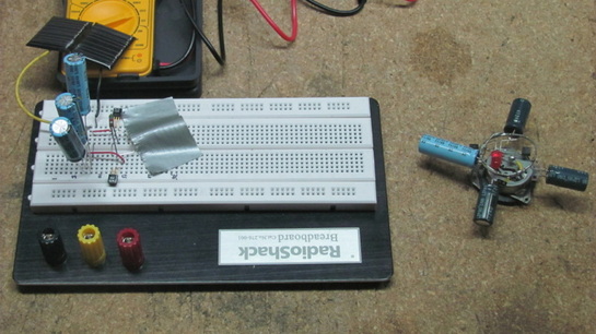
Figure 2: Two versions of Symet. On the left, you can see Symet 2 breaboarded and being tested. On the right, you can see my original attempt which, due to lack of prototyping, remains dysfunctional.
For those unfamiliar with a breadboard, it is really just a series of plugs wired together, some in series, some in parallel. The plugs are the size of typical component leads and, thus, allow for the quick swapping of parts. Jumper cables can be used to string together various rows (which are in series), either in series of in parallel. In Figure 2, you can see the two transistors (small back things), the three capacitors (large blue things), the solar cells (set off to the top) and even the resistor (small brown tube in the middle). The LED is covered by gray tape because high intensity light can sometimes damage flashing LEDs. The motor is not wired into the circuit yet.
After getting everything hooked up (including my original motor) I was disappointed to see no activity in my unassembled Symet. I began taking current and potential (voltage) readings with my multimeter to see what was wrong. By the time all was said and done, I had to use math to solve my problem (as is usually the case in electronics).
After getting everything hooked up (including my original motor) I was disappointed to see no activity in my unassembled Symet. I began taking current and potential (voltage) readings with my multimeter to see what was wrong. By the time all was said and done, I had to use math to solve my problem (as is usually the case in electronics).
Sizing the Motor
The basic problem that I had been having in my circuit, it turned out, was an improper balance between capacitors and motor load. The FLED circuit is pretty simple in nature. It takes a raw potential and current, as set by the solar cells, and trickle charges the bank of three capacitors. I was using three 2200 uF (microfarad) capacitors for my capacitor bank. Wired in parallel, as they were, that gave me a grand total of 6600 uF when all was said and done. Well, according to Wikipedia (and actual electronics books) a Farad is equal to current times time divided by potential. In terms of units, this means:
F = (A * s) / V
...where F symbolizes Farads (the unit of capacitance), A symbolizes Amperes (the unit of current), s stands in for seconds, and V symbolizes volts (the unit for potential). Originally I was using a motor that I pulled out of an old CD player. This motor was rated at a 3.5 volt operational load. This means that my capacitor bank was only capable of delivering 0.0066 uF * 3.5 V of current for 1 second. In other words, my capacitors could only deliver 0.0231 A, or 23.1 mA (milliAmps) to my motor over one second. Well my motor was rated to operate at 3.5 V and 200 mA or so. So, obviously, I was not delivering enough current to my motor.
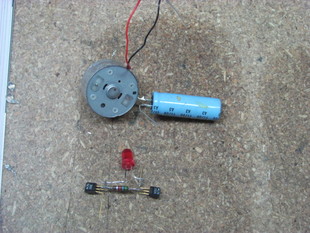
Figure 3: My low-load motor pictured with my
initial assembly of the FLED engine.
initial assembly of the FLED engine.
I had two options. I could add a lot more capacitors (0.2 A * 1.0 sec / 3.5 V = 57,142 uF worth), or I could use a smaller motor. Since I couldn't scrounge up three 20,000 uF capacitors, I opted for the second choice. I ended up scrapping a small motor from an old cassette deck similar to the one found here. The motor I used was basically rated at the same 12 mA at 2 V operating load as the one sold by Solarbotics. Using some quick math, I found that motor would be able to operate for:
time = F * V / A
time = 0.0066 F * 2.0 V / 0.012 A
time = 1.1 seconds
... 1.1 seconds in optimal conditions. Thus, all I had to do was swap the motor and the rest of the circuit should work. Sure enough, I plugged in the motor depicted in Figure 3, and my breadboarded Symet wiggled to life.
time = F * V / A
time = 0.0066 F * 2.0 V / 0.012 A
time = 1.1 seconds
... 1.1 seconds in optimal conditions. Thus, all I had to do was swap the motor and the rest of the circuit should work. Sure enough, I plugged in the motor depicted in Figure 3, and my breadboarded Symet wiggled to life.
Final Assembly
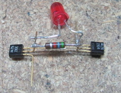
Figure 4: The final assembly of the FLED
solar engine.
solar engine.
With Symet trying to scoot about while breadboarded, I knew I was ready to begin assembling the little guy for real. The full construction instructions can be found, courtesy of solarbotics, in the pdf located here.
The first step is to assemble the two transistors, the resistor, and the FLED in a particular configuration. The resistor gets set between the collector of the 3904 transistor and the base of the 3906 transistor. The base of the 3904 transistor gets soldered directly to the collector of the 3906. The FLED cathode gets soldered to the emitter of the 3904 and the anode of the FLED gets soldered to the base of the 3906 (same node as one resistor end). The emitter of the 3906 will remain unanchored initially as it gets soldered to a conductive ring later. Similarly, the emitter of the 3904 will get soldered to the motor body later. Once these solder connections are made, you should end up with an FLED engine that looks similar to mine depicted in Figure 4.
The first step is to assemble the two transistors, the resistor, and the FLED in a particular configuration. The resistor gets set between the collector of the 3904 transistor and the base of the 3906 transistor. The base of the 3904 transistor gets soldered directly to the collector of the 3906. The FLED cathode gets soldered to the emitter of the 3904 and the anode of the FLED gets soldered to the base of the 3906 (same node as one resistor end). The emitter of the 3906 will remain unanchored initially as it gets soldered to a conductive ring later. Similarly, the emitter of the 3904 will get soldered to the motor body later. Once these solder connections are made, you should end up with an FLED engine that looks similar to mine depicted in Figure 4.
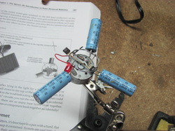
Figure 5: Symet near completion suspended
from one of my 'helping hands' workstation tools.
from one of my 'helping hands' workstation tools.
With the FLED engine assembled, the next step is to prep the body of Symet. Symet relies on its symmetrical (nearly symmetrical in my case) shape to bounce off of obstacles. Thus, the first step in the body construction is to solder all of the cathodes of the capacitors to the motor body in such a manner that the capacitors stick outward from the center of the motor. These capacitors get used as 'feelers' by Symet which allow it to bounce off of objects. Really, they are the only form of sensory (touch) input that Symet has. With the capacitors so soldered, a conductive ring needs to be soldered around their anodes (positive leads) to complete the circuit. With this basic shape constructed, the FLED engine can be mounted between the motor and the ring such that the 3904 emitter connects to the motor body, while the 3906 emitter connects to the ring. This assembly is depicted in Figure 4, suspended from a set of alligator clips in my shop.
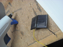
Figure 5: Notice the 'V' shape of the
solar array assembly. This simple geometry
ensures Symet will always have incident
light on its panels no matter its orientation.
solar array assembly. This simple geometry
ensures Symet will always have incident
light on its panels no matter its orientation.
The last few steps are pretty straight forward to finish the Symet. Hook the solar cell up such that the positive lead connects to the conductive ring while the negative lead connects to the motor body. As shown in Figure 5, I soldered and glued two solar panels together in such a manner to form an inverted V. I chose to do this for two reasons. Primarily, I wanted Symet to be able to get incident sunlight no matter how it tilted. Secondly, having two solar panels would allow Symet to charge its capacitors quicker and, thus, move more. As you work on little projects like this, you will find that simple little hacks like this can actually improve performance dramatically. My Symet, for instance, never seems to get stuck in a position where light can't impact its solar array.
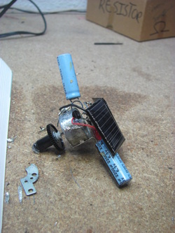
Figure 6: My final, functional version of Symet.
The only connections left to make were those for the motor. The cool thing about electric motors is that they don't really have a positive or negative lead. If you hook up the leads in 'reverse' the motor simply spins in the opposite direction. That said, for a robot like Symet, spin direction doesn't matter (the little bugger just scoots across whatever surface it's on randomly). All you have to do, therefore, is make sure you connect one motor wire to the collector of the 3904 transistor while you solder the other to the conductive ring where all the positive capacitor leads are connected.
Once I made this final connection, I held my breath while I shined a fluorescent lamp directly on Symet's solar panels. Sure enough, a few minutes later, the motor spun to life and Symet scooted across my workbench. Overjoyed at my final success, I glued the solar array in place (with an excessive amount of hot glue) and slapped a small wheel from inside a cassette deck to the motor axle. This gave Symet a better tilt and allowed it to hop a little more than a bare axle allowed. The final result is depicted in Figure 6 and in the video below.
Once I made this final connection, I held my breath while I shined a fluorescent lamp directly on Symet's solar panels. Sure enough, a few minutes later, the motor spun to life and Symet scooted across my workbench. Overjoyed at my final success, I glued the solar array in place (with an excessive amount of hot glue) and slapped a small wheel from inside a cassette deck to the motor axle. This gave Symet a better tilt and allowed it to hop a little more than a bare axle allowed. The final result is depicted in Figure 6 and in the video below.
Video 1: Here you can see my Symet's motor spinning and get an idea for
how long it takes between recharges.
how long it takes between recharges.
Lessons Learned
This was a simple enough project that I originally assumed it would be quick, easy, and painless. I was unpleasantly surprised. Being the first project that I cut my robotics teeth on, I learned quite a bit. Primarily, I learned that trying to slap a circuit together without first understanding the electrical loads and circuit architecture involved is doomed to failure. Really, the power balance throughout any circuit needs to be well understood to properly troubleshoot and configure the circuit. This is where the math described in the motor sizing section came into play.
Also, I learned how valuable it is to have a prototyping environment when starting a new project. Breadboarding the entire circuit and hot-swapping components allowed me to test parts and bits to ensure they were functional. It also allowed me to test my math before assembling anything. Diving straight into my original attempt without testing anything first was a doomed effort.
All in all, of course, this project was fun, and inspired me to do a lot more work. Since this effort, I've been slapping together an Arduino powered testbed robot which I should write up in the next couple of weeks. Until then, I hope you all had fun reading and learned something from my effort.
Best of Luck,
Brady C. Jackson

 RSS Feed
